RFID Basics!
imported ic.ac.uk · Tech · Geek · RFID
So, at the moment, I’m writing a presentation about the operation and the security implications of RFID. During the course of the random searches around the internet, I’ve found that there’s a lot of really, really cool work going with respect to RFID. Even more great than the output on the subject is who is studying it. Lots of really cool observations are coming out of the open source friendly community - some of the best presentations on the subject are from presentations at CCC. Along with projects like OpenPCD, this output is pretty cool!
However, that’s not really the point of this post. During the course of reading around, I’ve found that whilst there’s a lot of information around - there’s also a lot of FUD that surrounds that information. My presentation is trying to give people (with some physics background) a simple idea of what RFID is, and particularly how it works. Given that I’ve already done a quick summary of how RFID works, I figured I’d blog about it, so that I can add to the mush of material that you just can’t reference online.
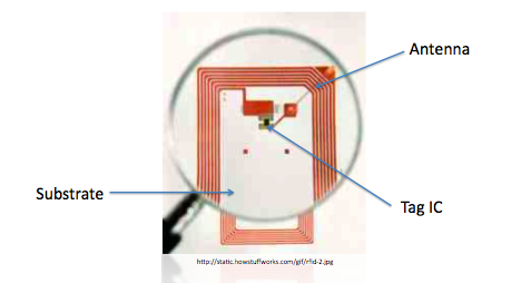
I’ll discuss a high frequency system - since cards such as MIFARE (which e.g. Oyster uses) work at around 13.56MHz. The RFID system consists of two elements - the reader, and the tag. Tags come in a number shapes - active, passive, and semi-passive. Really, it’s the passive tags that I’m interested in. The image below shows the anatomy of a (simple) passive tag. It’s composed of an antenna - running around the card, an IC, and a substrate that they’re both attached to.
The reader consists of a dipole-antenna, a transceiver, and some controlling electronics (this is hugely simplified, check OpenPCD for much more detail). Obviously, the consideration of the conversation between the reader, and the tag is the interesting part.
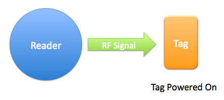
- The reader emits a signal from a dipole antenna at a fixed radio frequency. The magnetic field of the signal induces a current in the dipole antenna loop of the tag - hence powering it on.
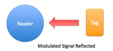
- The tag is now powered up, and a capacitor in the tag is charged, the current is trapped using a diode. The resulting voltage across the capacitor powers up the IC within the tag. In the really simple case that we’re considering - we’ll assume that this tag just has a unique ID, and isn’t doing anything interesting. The IC replays the unique tag ID (as a digital binary signal). The signal is fed into a transistor, causing the antenna to reflect/absorb more of the signal - hence modulating it.
- The modulated signal shows variations in the frequency which are dependent on the way in which the transistor responded to the input from the IC within the tag. This results in a load-modulated signal - the trace below shows the frequency distribution of the reflected signal from the tag.
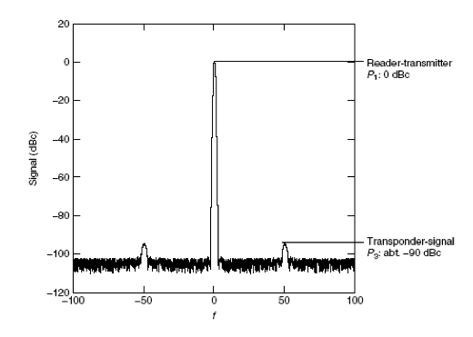
The RFID tag information is contained completely in the sidebands of the signal, and the figure above shows that compared to the reader-generated centre frequency - these are extremely weak. The 90dB difference accounts for some of the reason why RFID transmission range is so limited. - The modulated signal is received by the reader, where it is resolved into a tag ID.
This isn’t exactly the most exciting part of RFID, but its the basics of how the technology works, in a fairly friendly format I hope, and without a spin that’s trying to present any kind of agenda about RFID. There’s a lot more interesting things to look at, and blog about on this subject, so I’ll probably discuss those at some other time. But for the time being - I’m interested in this, and hope that this helps someone one day - questions/comments/corrections are welcomed to my mail address.